
4.0
Owner's of the Ashly Stereo Equalizer MQX-2310 gave it a score of 4.0 out of 5. Here's how the scores stacked up:


8
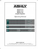
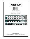
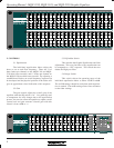
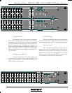
Operating Manual - MQX-2310, MQX-1310, and MQX-2150 Graphic Equalizer
7. TYPICAL APPLICATIONS
7.1General Tone Control
The graphic equalizer is a very useful device for
general tone shaping because it is intuitive and easy to
adjust. The visual reference provided by the slider posi-
tion gives an approximate idea of the frequency response
generated, with the lower frequencies on the left and
higher frequencies on the right. To use the power of an
equalizer effectively, you need to translate your idea of
the tone you want to produce into a range of numerical
frequencies. This is simple after a little practise. Here are
a few references which are useful for starting points:
Very low bass (the “wind” in a kick drum,
almost felt as much as heard -40Hz-80Hz.
The low register of a male voice - 200Hz
The low register of a female voice - 350Hz
Lower midrange (“warmth” frequencies) -
400Hz-1KHz
Upper midrange (“harshness”, snare drum “bite”,
“hot” sound) -2.5KHz-4KHz.
Sibilance (“sss” sounds, cymbal “sizzle”) - 8KHz-
15KHz.
Try using these starting points as a guide when
you want more or less of these types of sounds. Adjust
by ear from there. It is always a good idea to remember
that a little equalization usually works out much better
than a lot, and that there are many audio problems which
can not be solved with equalization alone.
7.2 Feedback Control
A graphic equalizer can be used to provide some
control over moderate feedback problems, but does not
have enough flexibility or resolution to handle severe situ-
ations. You will achieve the best results when you can
eliminate one or two feedback points by setting one or
two sliders for no more than a 6dB cut. Often you can
find a feedback point by boosting sliders in succession to
determine which frequency ranges contain the feedback
modes, and then cutting those ranges. Be very careful in
this process to avoid explosive feedback and possible sys-
tem and hearing damage! If you find feedback points
with many equalizer bands, remember that cutting every
band may not help (all you will do is reduce system gain).
The combination of a graphic equalizer for tone control
and a parametric equalizer (such as the Ashly PQX-571
or PQX-572) for feedback control is highly recommended.
7.3 Console Channel Equalization
Many mixing consoles provide only simple equal-
ization for individual channels. If your console has chan-
nel inserts, you can patch your graphic equalizer into a
channel that’s being used for something important and
use it to tailor the sound of this channel exactly the way
you want.
7.4 Large Room Equalization
Large rooms tend to suffer from multiple reflec-
tions with long time delays, long reverberation times, and
“ring-modes”, all of which lead to reduced intelligibility
and a generally “muddy” sound. As sound travels long
distances through the air, high frequencies are attenuated
more than low frequencies. In general, large rooms ben-
efit from some low frequency roll-off, high frequency
boost, and attenuation of ring mode frequencies. As in
the case of feedback control, a graphic equalizer can help
reduce an isolated ring-mode or two, but a tunable nar-
row-band equalizer such as a parametric is more effec-
tive here.
8. DESIGN THEORY
While most graphic equalizers look very much
the same, there are several important differences in the
circuitry used to implement various designs.
Perhaps the major differences are in the filters.
Some equalizers use a filter made of a capacitor, an in-
ductor, and a resistor, or “RLC” filter. The advantage
here is simplicity, but the real disadvantage is the induc-
tor itself. An inductor is a coil of wire with a core of
some sort. Inductors are susceptible to hum fields and
they are large and expensive.
Other equalizers use the same basic approach, but
replace the inductor with a “simulated inductor”, which
is actually a circuit comprised of an amplifier, a capaci-
tor, and a couple of resistors. This adds parts but is less
expensive than a real inductor. The problem with this
approach is that simulation is less than ideal; it produces
an inductor with high resistive loss resulting in poor curve
shape when used in a filter.
Another problem with “RLC” designs is that large
capacitors must be used for the lower frequency filters,
limiting the choice to large, expensive non-polar types or
electrolytic capacitors with poor audio performance. Also,


Find Your Products By Category
- Home Audio
- Portable Media
- Computer Equipment
- Musical Instruments & Equipment
- Power Tools
- Video Game
- Car Audio and Video
- Baby
- Lawn and Garden
- Communications
- TV and Video
- Household Appliance
- Kitchen Appliance
- Personal Care
- Photography
- Marine Equipment
- Laundry Appliance
- Fitness & Sports
- Automotive
- Cell Phone
Please Login
