System 10 Portable Camera-Mount Wireless Installation and Operation
6
System Operation
Turn down the headphone volume control and the camera/mixer
level before starting up the wireless system. Do not switch on the
transmitter yet.
Receiver on...
Press and hold receiver power button to turn receiver on. Power/Battery
indicator will glow green and the blue System ID number on the front
panel will illuminate.
If the Power/Battery indicator ashes green, the receiver’s battery
needs to be charged. You can charge the battery with the supplied
AC adapter and USB cable, following the instructions under Power
Connection on page 3. The LCD RX Battery Gauge will blink during
charging and a lightning bolt symbol will appear to the right of “RX.” The
Power/Battery indicator will glow red while the battery is charging and
turn green when charging is complete. Audio-Technica recommends
fully charging the internal battery before using the receiver for the rst
time. Average charge time takes 4 hours 30 minutes. To help maintain
the battery, it is best to operate the receiver (at least occasionally)
without the AC power supply and recharge when needed. Also, avoid
storing a fully charged receiver for a long period of time.
Transmitter on...
When the transmitter is switched on, the receiver's green pair indicator
will light, and two indicators light on the transmitter: the transmitter
Power / Battery / Mute status indicator will glow green; and the
transmitter blue System ID display will illuminate. The blue System ID
display on the transmitter and receiver turns off after 30 seconds to
conserve battery power; the transmitter Power / Battery / Mute status
indicator will remain illuminated, indicating transmitter status.
To re-illuminate System ID display, press the Power / Mute switch.
Note: this will alter the transmitter mute status. A slight touch of the
power switch toggles between muted and unmuted operation.
The transmitter’s Power / Battery / Mute status indicator glows red
when transmitter is muted, or green to indicate unmuted status. In a
low-battery situation, the Power / Battery / Mute status indicator begins
to blink.
The transmitters have a soft-touch power switch. When the switch is
set to “Mute” (red indicator LED), the transmitter produces RF with
no audio signal. When the switch is “On” (green indicator LED) the
transmitter produces both RF and audio. Excessive audio input to the
transmitter will cause the receiver’s red AF Peak indicator to light.
Receiver Attenuator
Typically, the receiver Audio Output Attenuator switch should be set
at 0dB, and the overall gain should be adjusted from the camera. If a
camera lacks that capability or if sensitivity is too high, use the Audio
Output Attenuator switch to reduce the gain until the signal does
not distort.
Input Level Adjustment
Input trimmer controls in the transmitters enable you to maximize
performance for a particular microphone or guitar sensitivity, or to
adjust for different acoustic input levels.
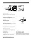
Adjusting Input Level — UniPak
®
Transmitter
Slide the battery cover off the transmitter and remove the screwdriver
from its clip. Using the screwdriver, gently turn the “VOL” (Volume
– Microphone/Instrument Level) all the way up (clockwise, toward
“H”). Check for excessive gain by speaking / singing into the
microphone at typically loud levels while watching the receiver’s
Peak Indicator. If the Peak indicator does light, turn the “VOL” control
slightly counterclockwise until the Peak indicator no longer lights with
maximum audio input to the transmitter.
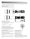
Adjusting Input Level — Handheld Transmitter
Unscrew the lower body cover and slide it off, exposing the screwdriver
and "LEVEL" (Gain Trimmer) control (Fig. C). Remove the screwdriver
from its clip. Gently turn the "LEVEL" control to its full clockwise
position (toward the side marked “H”), the factory setting. Check for
excessive gain by speaking/singing into the microphone at typically loud
levels while watching the receiver’s AF Peak indicator. If the AF Peak
indicator does light, turn the "LEVEL" control slightly counterclockwise
until the AF Peak indicator no longer lights with maximum audio input
to the mic/transmitter.
Return the screwdriver to its clip and close and secure the lower body.
No further transmitter gain adjustments should be needed, as long as
the acoustic input does not change signicantly.
CAUTION! The small trimmer controls are delicate; use only the
supplied screwdriver. Do not force the trimmers beyond their normal
190° range of rotation.
Return the screwdriver to its storage clip when not in use.
Setting System ID Number & Pairing your Transmitter and Receiver
Your system has been precongured at the factory to operate with no
other pairing setup required; it will work out of the box. That is, your
receiver and transmitter are already a digital pair, and they have been
assigned the same System ID number.
The pairing instructions outlined below will help you if you nd
it necessary to change system ID numbers in multiple-system
congurations, or pair a new transmitter to an existing receiver.
NOTE: System ID is an identical number assigned to a paired
receiver and transmitter for identication purposes. The System ID
number is not related to transmitting frequency. Due to the dynamic
nature of System 10 automatic frequency selection, the actual
transmitting frequencies may change during power-up or performance.
These frequency changes are seamless and imperceptible to the ear.
Pairing Receiver with Transmitters
Note: Up to eight transmitters may be paired with the receiver.
1. Turn the receiver and rst transmitter on.
2. Press the System ID button on the receiver to choose an ID number
from 1 to 8. The receiver’s display will show your new ID and begin
to blink.
3. Within 15 seconds, press and hold the Pair button on the receiver
for about one second. The Pair light will begin to blink green. The
receiver is now in Pair Mode.
Note: If the receiver Pair button is not pressed within 15 seconds,
the system ID number will revert to its previous setting.
4. Open the transmitter and press and hold its Pair button within 30
seconds of entering Pair Mode. The transmitter display will now
show the System ID number you have chosen on the receiver. The
receiver’s Pair light will glow steady, indicating you have successfully
paired your system.
5. To pair an additional transmitter, you must switch off rst transmitter
by pressing and holding its Power/Mute button. Turn the second
transmitter on and follow instructions 2-4 above, making sure to
assign a different System ID number to the new transmitter.


