

0
Owner's of the Axis Communications Car Video System Axis Communications Car Video System gave it a score of 0 out of 5. Here's how the scores stacked up:


AXIS M7014 Video Encoder
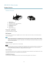
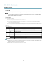
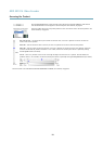
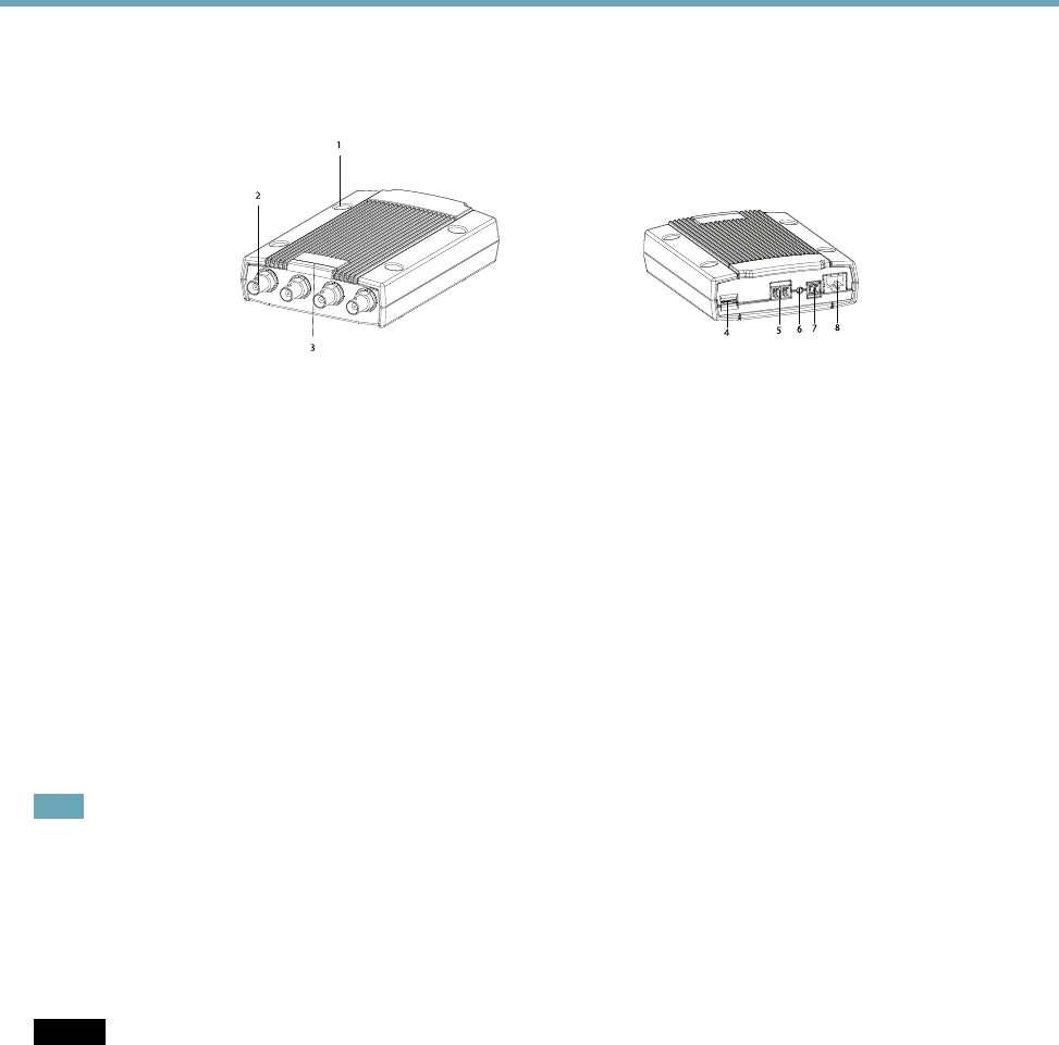
Hardware Overview
Hardware Overview
1
2
3
4
5
6
7
8
1.
Mounting holes
2.
Video input connectors
3.
LED indicators for power, status and network
4.
SD memory card slot (microSD)
5.
RS-485/RS-422 connector
6.
Control button
7.
Power connector
8.
Nework connector (PoE)
Connectors and Buttons
For technical specications, see page 49.
BNC Connector
Each video input is terminated using a coax/BNC connector. Connect a 75 Ohm coaxial video cable; the recommended maximum
length is 250 m (800 ft).
Note
75 Ohm video termination can be enabled/disabled for the video input through the product's web page at Video > Camera
Settings > Video termination. This termination is enabled on factory default. In cases where the product is to be connected
in parallel with other equipment, for optimum video quality, it is recommended that termination be enabled for only the last
device in the video signal chain.
Network Connector
RJ45 Ethernet connector. Supports Power over Ethernet (PoE).
NOTICENOTICE
NOTICE
The product shall be connected using a shielded network cable (STP). All cables connecting the product to the network switch
shall be shielded (STP) and intended for their specic use. Make sure that the network switch is properly grounded. For
information about regulatory requirements, see Regulatory Information, on page 2 .
Power Connector
2-pin terminal block for power input. Use a Safety Extra Low Voltage (SELV) compliant limited power source (LPS) with either a rated
output power limited to ≤100 W or a rated output current limited to ≤5 A.
RS485/RS422 Connector
Two terminal blocks for RS485/RS422 serial interface used to control auxiliary equipment such as PTZ devices.
5


Find Your Products By Category
- Home Audio
- Portable Media
- Computer Equipment
- Musical Instruments & Equipment
- Power Tools
- Video Game
- Car Audio and Video
- Baby
- Lawn and Garden
- Communications
- TV and Video
- Household Appliance
- Kitchen Appliance
- Personal Care
- Photography
- Marine Equipment
- Laundry Appliance
- Fitness & Sports
- Automotive
- Cell Phone
Please Login
