
0
Owner's of the Axis Communications Security Camera Axis Communications Security Camera gave it a score of 0 out of 5. Here's how the scores stacked up:

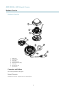

AXIS M3024–LVE Network Camera
Hardware Overview
NOTICENOTICE
NOTICE
The product shall be connected using a shielded network cable (STP) or an optical ber cable. All cables connecting the
product to the network shall be intended for their specic use. Make sure that the network devices are installed in
accordance with the manufacturer’s instructions. For information about regulatory requirements, see Electromagnetic
Compatibility (EMC), on page 2 .
I/O Connector
Use with external devices in combination with, for example, tampering alarms, motion detection, event triggering, time lapse recording
and alarm notications. In addition to the 0 V DC reference point and power (DC output), the I/O connector provides the interface to:
• Digital output – For connecting external devices such as relays and LEDs. Connected devices can be activated by the
VAPIX® Application Programming Interface, output buttons on the Live View page or by an Action Rule. The output will
show as active (shown under System Options > Ports & Devices) if the alarm device is activated.
• Digital input – An alarm input for connecting devices that can toggle between an open and closed circuit, for example:
PIRs, door/window contacts, glass break detectors, etc. When a signal is received the state changes and the input becomes
active (shown under System Options > Ports & Devices).
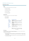
SD Card Slot
A microSD card (not included) can be used for local recording with removable storage. For more information, seeTechnical
Specications, on page 52.
NOTICENOTICE
NOTICE
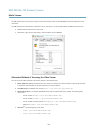
To prevent corruption of recordings, the SD card should be unmounted before removal. To unmount, go to Setup > System
Options > Storage > SD Card and click Unmount.
Control Button
The control button is used for:
• Resetting the product to factory default settings. See page 47.
• Connecting to an AXIS Video Hosting System service. See page 40. To connect, press and hold the button for about 1
second until the Status LED ashes green.
• Connecting to AXIS Internet Dynamic DNS Service. See page 40. To connect, press and hold the button for about 3 seconds.
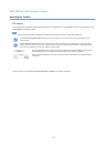
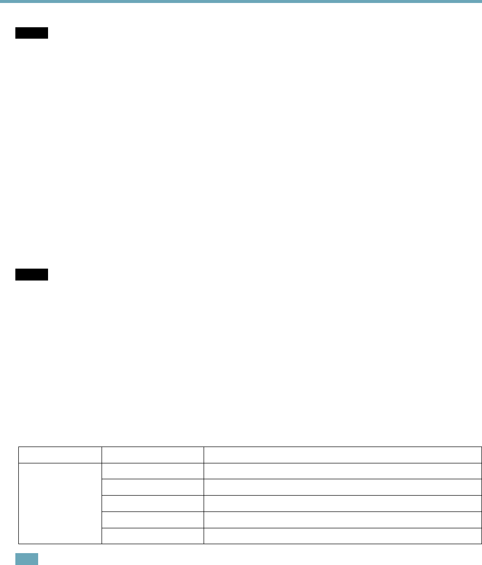
LED Indicators
LED
Color
Indication
Unlit
Connection and normal operation
Amber
Steady during startup. Flashes during rmware upgrade.
Amber/red Flashes amber/red if network connection is unavailable or lost.
Red Flashes red for rmware upgrade failure.
Status
Green Shows steady green for 10 seconds for normal operation after restart.
Note
• The Status LED can be congured to be unlit during normal operation. To congure, go to Setup > System Options > Ports
& Devices > LED. See the online help for more information.
• The Status LED can be congured to ash while an event is active.
• The Status LED can be congured to ash for identifying the unit. Go to Setup > System Options > Maintenance .
6


Find Your Products By Category
- Home Audio
- Portable Media
- Computer Equipment
- Musical Instruments & Equipment
- Power Tools
- Video Game
- Car Audio and Video
- Baby
- Lawn and Garden
- Communications
- TV and Video
- Household Appliance
- Kitchen Appliance
- Personal Care
- Photography
- Marine Equipment
- Laundry Appliance
- Fitness & Sports
- Automotive
- Cell Phone
Please Login
