
0
Owner's of the Axis Communications Security Camera Fixed Dome Network Camera gave it a score of 0 out of 5. Here's how the scores stacked up:


AXIS M3027–PVE Fixed Dome Network Camera
Technical Specifications
Function/group
Item
Specications
Dimensions
(Diameter x
Height)
132 x 73 mm (5.1 x 2.8 in)
Weight
740 g (1.6 lb.)
Included
accessories
Installation Guide, Installation and Management Software CD, drill hole template,
Windows decoder 1-user license, Resitorx L-key, terminal block connector
Optional
accessories
For indoor use:
AXIS T94F01D Pendant Kit with Network Cable Coupler Indoor
AXIS T94F01L Recessed Mount Kit with Network Cable Coupler Indoor
For outdoor use:
Network Cable Coupler IP66 (can t inside AXIS T94F02D Pendant Kit)
AXIS T94F02D Pendant Kit with sunshield
For indoor or outdoor use:
AXIS T94F01M J-Box/Gang Box Plate and Network Cable Coupler Indoor (coupler must be
placed in waterproof area)
Skin covers
AXIS T91 Mounting Accessories
AXIS T94F01P Conduit Back Box
Video
management
software
AXIS Camera Companion (included), AXIS Camera Station and video management
software from Axis’ Application Development Partners (not included). See
www.axis.com/products/video/software
Languages
German, French, Spanish, Italian, Russian, Simplied Chinese, Japanese, Korean,
Portuguese
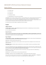
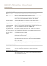
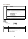
Connectors
I/O Connector
4–pin terminal block for:
• Auxiliary power (DC output)
• Digital Input
• Digital Output
• 0 V DC (-)
1
2 3 4
Function Pin Notes
Specications
0 V DC (-)
1
0 V DC
DC output
2
Can be used to power auxiliary equipment.
Note: This pin can only be used as power out.
12 V D C
Max load = 15 mA
Digital Input
3
Connect to pin 1 to activate, or leave oating (unconnected)
to deactivate.
0 to max 30 V DC
Digital Output
4
Connected to pin 1 when activated, oating (unconnected)
when deactivated. If used with an inductive load, e.g. a relay,
a diode must be connected in parallel with the load, for
protection against voltage transients.
0 to max 30 V DC, open drain,
100 mA
64


Find Your Products By Category
- Home Audio
- Portable Media
- Computer Equipment
- Musical Instruments & Equipment
- Power Tools
- Video Game
- Car Audio and Video
- Baby
- Lawn and Garden
- Communications
- TV and Video
- Household Appliance
- Kitchen Appliance
- Personal Care
- Photography
- Marine Equipment
- Laundry Appliance
- Fitness & Sports
- Automotive
- Cell Phone
Please Login
